West Kimberley Regional Prison, Australia
Abstract
Douglas Partners Pty Ltd, geotechnical and environmental consultant, undertook a geotechnical investigation for the proposed West Kimberley Regional Prison located in Derby, Western Australia, in 2008 and 2009. The site is underlain by Pindan Sand, a red-brown aeolian clayey sand that exhibits collapse potential. The aim of this paper is to provide an example of the approach adopted by the industry to identify and assess collapsing soils. The paper will first introduce the Pindan sand then guide the reader through the steps adopted for the assessment of the soil collapse potential. This includes a desktop study, field sampling and testing and a selective laboratory testing programme. Timing requirements and the cyclone season did not allow a lengthy programme of laboratory testing using double oedometer tests as proposed by Jennings and Knight (1975). Therefore, an attempt was made to correlate a large number of field density data with a limited amount of collapse potential results. Also, a comparison was made between collapse potential results on sample recovered at the end of the dry season and shortly after the wet season. The last part of the paper addresses the implications of the occurrence of collapsing soils on the civil project. In particular, two approaches were adopted for the analysis of the settlements under the proposed foundation systems, and for the analysis of laterally loaded piles.
1. Presentation of the Study
Douglas Partners Pty Ltd, geotechnical and environmental consultant, undertook a geotechnical investigation for the proposed West Kimberley Regional Prison located in Derby, Western Australia, in 2008 and 2009. The 25 ha site is underlain by Pindan Sand, a red-brown aeolian clayey sand that exhibits collapse potential. A significant amount of testing was undertaken for this project to assess the soil collapse potential and its impact on the civil project. The process adopted by the Consultant to investigate collapsing soils within the industry constraints such as budget, timing and contract scope, together with noteworthy results on the collapsing soil encountered, are described in the next sections.
2. Introduction to Pindan Sand
Pindan sand is widespread in the Kimberley and Pilbara regions of north Western Australia. This material exhibits collapse potential, that is, in the words of the Australian Standard AS2870 [1], it is a “weakly cemented soil that is subject to large settlements under load as a result of degradation by water on the cementing agent”
It is a typically red-brown, fine to medium grained aeolian clayey sand and silty sand, with up to 35% fines. It is described on the 1:250,000 Derby environmental geological sheet [2] as “red sand, fine to medium, minor silts, aeolian” of the Quaternary period of the Cainozoic era. A representative grading curve for a sample from the prison site is given in Figure 1.
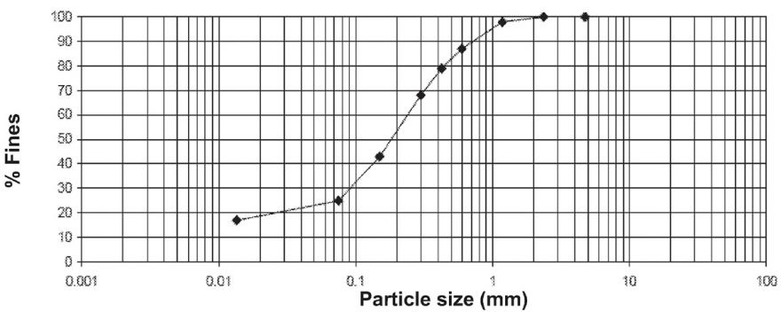
Figure 1 – Representative Particle Size Distribution of a Pindan Sand Sample from the West Kimberley Regional Prison Site
Results of an analysis of Pindan sand using scanning electron microscopy and X-ray diffraction was undertaken by S. Emery [3] for a site in the nearest town (Broome, 170 km away) and indicated that the clayey sand typically comprises 75% of sub angular quartz sand grains cemented by bridges of iron oxide and aluminium hydroxides (in the form of iron-kaolinite).
Typical Atterberg limits for the fraction passing 425 µm for clayey Pindan Sand in North Western Australia are:
- liquid limit of between 18% and 22%;
- plasticity index of between 4% and 11%;
- linear shrinkage of between 0% and 4%.
A representative compaction curve using modified compaction energy for a sample recovered from the prison site is given in Figure 2.
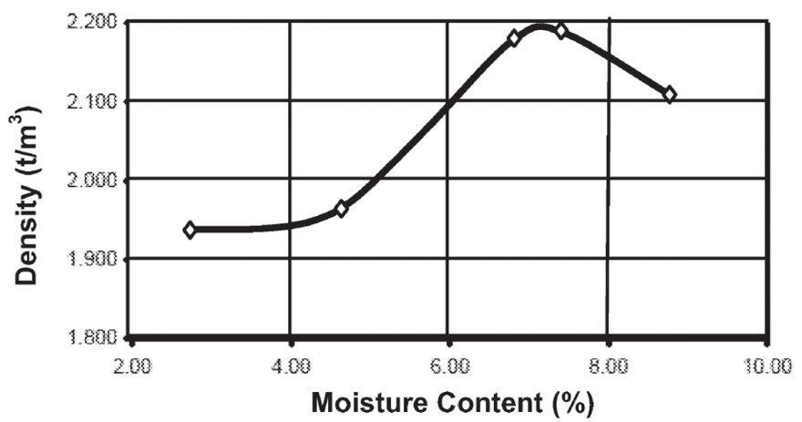
Figure 2 – Representative Compaction Test of a Pindan Sand Sample from the West Kimberley Regional Prison Site
Ground conditions beneath the site of the West Kimberley Regional Prison generally include 0.3m of loose silty sand, overlying clayey sand (Pindan Sand) encountered to the base of the test pits terminated at depths of up to 4.5 m. The Pindan sand exhibited some high apparent cohesion (hard). Blow counts of more than 25 blows per 150 mm were generally recorded when using a hand held dynamic cone penetrometer with a 9 kg hammer dropping from a height of 510 mm [4].
3. Data Gathering
3.1 Desktop Study
The occurrence of Pindan sand and its possible collapse potential was identified at proposal stage of the contract and was corroborated by the results of a desktop study using aerial photographs and published information such as the geological map.
3.2 Field Work
Field work was undertaken in two stages and started in September 2008 prior to the cyclone season that precludes access to the site owing to flooding and poor trafficability. The first stage included test pitting at about 55 locations to assess the ground conditions and undisturbed sampling for subsequent soil laboratory assessment of the soil collapse on six samples. Results of this first stage indicated that ground conditions across the site were relatively uniform and confirmed the collapse potential of the ground.
Following the wet season, additional fieldwork was undertaken in April 2009 for further assessment of collapse potential. This second stage included the excavation of eight test pits to 4.5m depth with in situ nuclear densometer testing [5] at various depths in each test pit. Undisturbed samples, 150 mm diameter, were also collected.
The main limitations of this work were:
- The project design deadlines, exacerbated by the cyclone season that precluded the collection of soil samples dry enough for the assessment of representative collapse potential; and
- The duration of each laboratory test and the equipment requirements. A double oedometer test as proposed by Jennings and Knight [6] takes approximately a fortnight to a month depending on the loading path. Also, availability of suitable testing apparatus is low in Western Australia. It should be noted that a single laboratory was employed for all specialized testing to ensure consistency of method and repeatability of the results.
The above limitations resulted in a relatively limited amount of data for the assessment of collapsing potential beneath the site, with 4 laboratory collapse potential results on samples collected prior to the cyclonic season and 8 results on samples collected following the cyclonic season.
An attempt was made to extend the limited information by extrapolating the available results on collapse potential to other locations by using in situ density data. The attempt to establish a relationship between collapse potential and in situ density is described in a following section.
Undertaking in situ testing using plate load testing with inundation was suggested by the Consultant to increase the level of confidence in the results on collapsing potential. In this test, the soil is initially loaded with a known load in order to apply a target bearing pressure. The plate load is instrumented in order to monitor its displacement. In a second stage, the soil is inundated, thus inducing the collapse of the soil. The collapse displacement is recorded. This test can be undertaken at several depths to assess the variation of soil collapse potential with depth. This testing was not undertaken following discussion with the Civil Engineer, Architect and Client owing to time constraints and a level of site characterisation required for the project that was considered adequate without additional testing.
4. Results on Collapse Potential
4.1 Double Oedometer Testing
The test described by Jennings and Knight [6] is based on the oedometer test. A simplified description of the test is given below. The soil is divided into two sub samples. One sample is at field moisture condition and the other one is soaked. A consolidation test is undertaken on each sample and provides the variation of the soil void ratio under increasing load. The soaked sample collapses during the test. Following various adjustments, comparison of the two consolidation curves provides the elastic settlement and the settlement that results from the collapse of the soil, for a range of loading pressures.
Jennings and Knight suggested a classification based on the soil collapse (in % or cm of collapse settlement perm of soil) under a loading pressure of 200 kPa.
4.2 Collapse Potential Classification (Jennings and Knight)
Laboratory testing results on collapse unit settlement under a bearing pressure of 200 kPa are plotted in Figure 3 together with the classification suggested by Jennings and Knight. It is emphasised that results on collapse potential are available for a limited number of tests and thus may not be representative of the whole site. The results indicate unit collapse settlements of between 5% and 7% at 0.3 m depth, less than 3% at 1 m depth and reducing to less than 1% at 3.5 m depth. This indicates that the shallow Pindan sand is collapsible and can be classified as “trouble” at a depth of
0.3 m and up to “moderate trouble” below 1 m, in accordance with Jennings and Knight [6].
4.3 Variation of Total Unit Settlements with Bearing Pressures
Total settlement is the sum of elastic settlement and soil collapse and is measured by the double oedometer test for various loading pressures. The total unit settlements for various bearing pressures can be derived from the collapsing test results and are plotted in Figure 4.
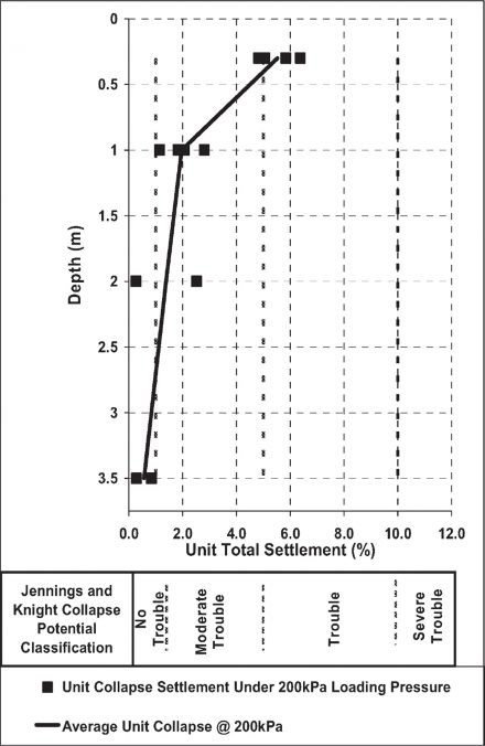
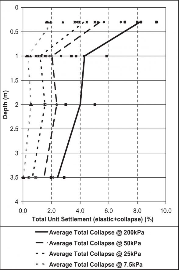
Figure 3 (Left) – Laboratory testing Results on Collapse Settlement under 200 kPa vs Depth and Jennings and Knight Collapse potential Classification
Figure 4 – Total unit Settlement Vs Depth
4.4 Relationship between Soil Density and Collapse Potential
Time constraints prevented a comprehensive amount of testing on collapse potential using the method detailed in Jennings and Knight [6]. Therefore, an attempt was made to correlate the available results on collapse potential to additional locations using soil density data. Soil density from laboratory data is plotted against total unit settlement and collapse unit settlement (both in % or cm/m) in Figure 5. It should be noted that laboratory results of soil density from undisturbed samples were preferred to density results from in situ nuclear testing, owing to a better quality control of the testing. Similar plots were obtained using the nuclear densometer results. Results in Figure 5 indicate greater total unit settlement for soils with densities of less than 1.6 t/m3, typically measured at 0.3 m depth beneath the site. It can be noted that there is no apparent decrease of unit settlement for soil densities of between 1.6 t/m3 and 1.9 t/m3 that were encountered between depths of 1.0 m and 3.5 m beneath the site
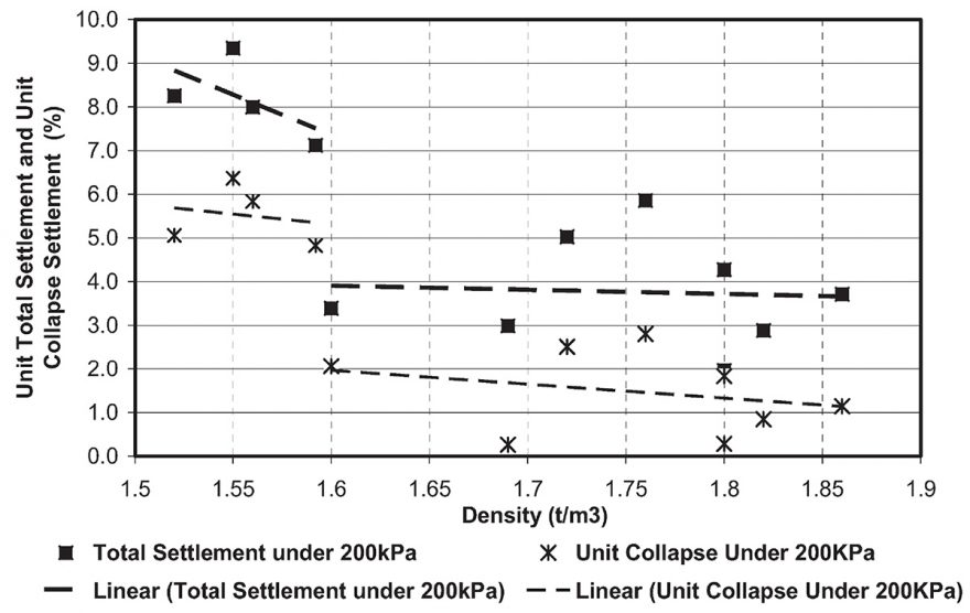
Figure 5 – Correlation between Soil Density and unit Settlement (Total and Collapse Settlement)
4.5 Discussion on Soil Densities and Impact on Soil Collapsing Results
Soil dry densities across the site were compared with soil dry densities available for the samples that were tested for collapsing potential.
Comparison of the data envelopes suggests:
- to a depth of 1 m, the sample of data for which collapsing soil results are available, is representative of the soil density across the site;
- beneath a depth of 2 m, the sample of data for which collapsing soil results are available shows an increase of density with depth whereas the set of soil density data for the entire site suggests that soil densities across the site appear to be relatively constant with depth (below 2m), ranging from
1.62 t/m3 to 1.77 t/m3. As soil densities appear to be similar at 2.0 m and 3.5 m, it was assumed that collapse potential were similar at both depths. It was also assumed that no significant collapse occurs below 3.5 m depth, for the purpose of the analysis detailed in the following sections.
4.6 Impact of Soil Moisture
Using the double oedometer test, soil collapse is measured on a soaked sample and compared to the settlement observed on a sample at field moisture condition. A concern was that the laboratory results for samples recovered after the cyclone season possibly underestimate the soil collapse potential and could not be compared with results obtained on samples collected prior to the wet season. Moisture content of samples at 0.3 m recovered prior to cyclonic season were less than 1%, compared to between 6% and 10% for samples recovered following the wet season. This situation was managed by including a suitable level of conservationism in the analysis in order to take into account a possible greater collapsing potential than measured on the samples recovered after the cyclonic season.
4.7 Conclusions on Soil Collapse Potential across the Site
The collapse potential that was assumed for the soils beneath the prison site for the subsequent analysis is shown in Table 1.

Based on the results of the analysis, ranges of unit total settlements estimated for several bearing pressures and depths below natural ground surface are presented in Table 2.

5. Effect of Collapsing Soils on the Civil Project
5.1 Settlement under the proposed Footing Systems
Settlements were calculated under a given footing load by dividing the soil under the footing into layers and allocating an average stress applied by the footing over the height of each layer using Boussinesq stress attenuation method [7]. A unit total settlement was allocated to each layer using the results from Table 2, based on the depth of the layer and the stress at this level. Settlements for each layer over the depth of the influence of the footing were summed to provide the total settlement under the footing. This approach is illustrated in Table 3 for a 1.0 m square pad footing founded 0.4 m below natural ground level and applying a 50 kPa bearing pressure. Another approach was to calculate an elastic soil deformation modulus, using the elastic equation (Deformation Modulus = Stress / Strain) for each unit total settlement from Table 2 and to use this data into an in-house settlement program based on elastic theory. Both approaches gave similar results.

The recommended earthworks preparation prior to construction of the foundation systems included the excavation of the collapsing ground to a suitable depth under the proposed buildings and its replacement in a controlled manner. The aim of the site preparation was to obtain a controlled foundation material to a suitable depth below foundation levels in order to decrease the risk of settlement from possible ground collapse to less than 20 mm after construction. Other site preparation procedures were considered, such as impact rolling, but considered less applicable to the project.
The approach described above for the analysis of settlement was also used to assess depths of over excavation under the base of the footings. In the analysis, a null collapse potential and a high deformation modulus were allocated over the depth of over excavation in order to control settlement results for the layer of excavated, replaced and compacted material. An example of results is given in Table 4 below.

5.2. Effect of Collapsing Soils on Laterally Loaded Piles
Bored piles, 600 mm diameter, are proposed to support the perimeter fence of the prison.
The lateral behaviour of the piles was assessed for several loading scenarios provided by the Civil Engineer, using the software Pygmy [8], a finite element computer software package that uses the p-y method to model the interaction between piles under lateral loading and foundation material.
Two scenarios were assumed regarding ground conditions:
- Scenario 1: the ground has been suitably compacted to a depth of 1.5 m, for instance after reworking of the soil or using an impact roller. The pile length was assumed to be 3.5 m for this case, as suggested by the Civil Engineer based on the suitable behaviour of similar structures piled in collapsing Pindan sand in Broome (170 km away).
- Scenario 2: the top 1.5 m of the soil profile has lost strength as a result of inundation and collapse. The pile length was assumed to be 3.8 m for this case.
Both scenarios were modelled at serviceability and ultimate limit states.
Several p-y formulations were used to define the lateral interaction between piles and foundation material. The behaviour adopted for shallow Pindan sand in a collapsed state either assumed the pile to be free standing over the depth of collapse or adopted the lateral load transfer criterion recommended by the American Petroleum Institute for sand [8] in a loose state. The underlying uncollapsed Pindan sand was either modelled using a p-y formulation for dense sand (API criterion) or a simple linear perfectly plastic model for very stiff clay, owing to the cohesive appearance of the Pindan in a dry condition. Combination of the above approaches resulted in a range of pile head displacement estimates.
Results of the analysis indicated pile head horizontal displacement values of between 2 mm and 10 mm at serviceability state and 5 mm to 15 mm at ultimate state. If it is assumed that the collapsed Pindan sand does not contribute to lateral resistance (i.e. the pile is free standing over the depth of collapsed soil) and if the underlying uncollapsed Pindan sand is modelled as dense sand, then the model indicated a pile head displacement of 100 mm at ultimate limit state for collapsed soil to a depth of 1.5 m. This displacement value is significantly greater than results given when using other p y curves and was considered as a very conservative upper limit.
Based on the above results, it was decided not to improve the ground along the fence provided that the ground surface along the perimeter is bitumen sealed and graded away from the fence towards swales located approximately 10 m away on each side of the fence, thus minimising the potential for water ingress into the foundation material. Regular inspections and maintenance of the seal around the fence was also recommended.
A sensitivity analysis of the impact of depth of collapsing soil on the pile head displacement was undertaken at serviceability limit state. The analysis was undertaken for only two cases of p-y curve and the greatest displacement values were plotted in Figure 6. These results should be considered indicative. Differences in pile head displacements using other p-y curves are estimated to be of the order of 5 mm for a depth of collapsing soil of 1.5 m, and 50 mm for a depth of collapsing soil of 3.8 m.
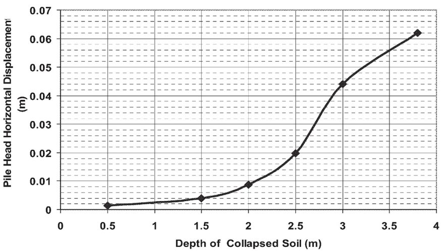
Figure 6 – Pile Head Displacement vs Depth of Collapsing Soil
3.8 m long, 0.6 m diameter pile
Lateral Load = 18 kN, Moment = 50kN.m
6. Conclusion
A case study of assessment of collapsing soils encountered during a geotechnical investigation was described. Although timing, cost and scope of the geotechnical investigation are invariably limiting factors for a detailed assessment of such soils and their implications on a civil project, it is believed that an adequate degree of assessment was achieved for the site of the West Kimberley Regional Prison in Derby. In this instance, the level of accuracy of the study was defined from discussions with the civil engineer, Architect and Client. It is also believed that noteworthy results were achieved and could possibly be used beyond the scope of the study.
Douglas Partners would like to thank the Department of Corrective Services of Western Australia for their authorisation to present these results.
References:
- Australian Standard AS1728 -1996, Footings – Residential Slabs and Footings – Construction, 1996
- Geological Survey of Western Australia, Australia 1:250,000 Geological Series, Derby, Western Australia , Sheet SE 51-7, 2nd Edition, 1980.
- S.J. Emery, S. Materson and M.W. Caplehorn, Sand-clay Pindan material in pavement as a structural layer, 21st AARB and 11th REAM Conference, Cairns , Australia, May 2003
- Australian Standard AS 1289.6.3.2-1997, Soil Strength and Consolidation Tests-Determination of the Penetration Resistance of a Soil – 9 kg Dynamic Cone Penetrometer Test, 1997
- Australian Standard AS1289.5.8.1-1995, Soil Compaction and Density Test-Determination of field density and field moisture Content of a Soil Using a Nuclear Surface Moisture-Density Gauge, 1995
- J.E. Jennings and K. Knight (1975), Guide to Construction on or With Materials Exhibiting Additional Settlement Due to “Collapse” of Grain Structure, Sixth Regional Conference for Africa on Soil Mechanics & Foundation Engineering, Durban, South Africa, September 1975
- GB Sowers and G.F.Sowers – Introductory Soil Mechanics and Foundations. 2nd edition, McMillan Co, p145, 1961.
- University of Western Australia, Program PYGMY, p-y analysis of laterally loaded piles under general loading, October 2000.
- E.A. Nowatzki, M.M. Ali and D.E. Myers (1989), A Use of Geostatistics to Predict the Occurrence of Collapsing Soil, Proceedings of the Congress on Foundation Engineering, Current Principles and Practices, Evanston Illinois, June 25-29, 1989.

