Abstract
Three case studies of filling works are reviewed. In the first case, a deep quarry was backfilled with a combination of clays, ripped shale and ripped sandstone under controlled conditions. Settlement monitoring was carried out over a period of two years to measure the consolidation of the filling. The settlement results are presented and interpolation carried out to estimate the long term settlement of the deep filling in preparation for an industrial building on the site. The second and third case studies are two separate sites where reactive clay filling up to 2 m deep was placed and compacted. In both cases, the clay filling was compacted dry of optimum moisture content and over-compacted. Over time, the clay filling swelled resulting in movement of ground bearing slabs, which affected the performance of the overlying buildings. The study compares the material properties, the compaction testing results, the changes in moisture content and the swelling.
Keywords: filling, settlement, swelling clay filling
1. Introduction
As practising geotechnical engineers, we routinely present recommendations to our clients regarding compaction requirements for filling in terms of minimum and maximum dry density ratios relative to laboratory maximum dry density values and moisture content ranges relative to laboratory optimum moisture contents. However, detailed earthworks specifications are frequently prepared by other nongeotechnical professionals and quite often such specifications are simple reproductions of a previous document, rebadged for the new project. At times, their appropriateness is questionable.
This paper presents three such case studies. The authors consider that each case study provides some insight as to the importance of preparing earthworks specifications that are not only appropriate for the civil works but also consider the type of material being placed and the long term application and serviceability requirements of the completed filling volume.
2. Case 1 – Backfilling of a Deep Quarry
This case involves the backfilling of a quarry some 30+ m deep in preparation for subdivision into one or more industrial lots, as part of a larger industrial subdivision located in western Sydney. The work was carried out on behalf of the then site owner between 2005 and 2009 prior to its sale and subsequent development in 2011.
The quarry base occupied an area of approximately 190 m by 190 m, increasing to 280 m by 310 m at the top of the quarry. The base of the quarry varied in surface level by up to 10 m. On completion of backfilling the finished surface level varied by 7 m from the western to eastern sides. Total filling depths varied between approximately 18 m and 39 m, reducing rapidly to 0 m over the buried inclined perimeter quarry sides.
2.2 Backfilling Process
Quarry backfilling was near-continuous for a period of almost 4 years. In total, 1 784 200 m3 of filling was placed, with approximately 650 000 m3 sourced from on site or from immediately adjacent industrial lots within the greater subdivision. The remainder of the filling comprised virgin excavated natural material (VENM) that was sourced from 140 external sites spread throughout the greater Sydney environs. Filling was placed, moisture conditioned, spread and compacted by excavators, trucks, scrapers, dozers, compactors, self-propelled pad foot rollers and water carts.
2.3 Earthworks Specifications
In addition to strict environmental controls that governed the importation of VENM filling, geotechnical controls were also specified and monitored by Douglas Partners. They included:
- Filling placed in accordance with a Level 1 inspection and testing standard, as defined in AS3798, with experienced geotechnicians on site during the placement and compaction of filling.
- Senior geotechnical engineers experienced in earthworks regularly attending site to monitor backfilling progress and to take an active role in the approval process for imported soil.
- Filling consisting of VENM that is capable of being compacted to form a stable filling embankment.
- Filling tested at a minimum frequency of 1 test / 5000 m3 for particle size distribution and Atterberg limits tests (liquid limit < 65%, plasticity index < 35%).
- Maximum particle sizes less than 150 mm after compaction (initially based on a maximum layer thickness of 300 mm but later relaxed to less than 300 mm maximum particle size after compaction based on an acceptable 500 mm layer thickness).
- Density tests carried out at a minimum frequency of 1 test / 500 m3 of filling placed. Testing was undertaken to confirm the following minimum compaction and moisture content requirements:
- Clayey Soils (defined as soils containing more than 40% clay fines) – 100% Standard;
- Granular Soils – 98% Standard.
- Moisture content of between 3% dry and 2% wet of standard optimum moisture content.
- Filling to satisfy a maximum weighted plasticity index value of 1500, which is obtained by multiplying the soil plasticity index with the percentage value passing the 425 micron sieve. This is a compromise that allows an ever reducing small proportion of the filling to contain moderate to high plasticity fines.
Granular soils were placed within the lower 8 m to 10 m depth of the quarry platform to limit differential performance of the filling across areas of uneven filling thickness. Granular filling generally comprised ripped sandstone and low to medium strength ripped siltstone (and to a lesser extent shale).
2.4 Earthworks Test Results
In total, 3493 density tests were undertaken, equating to 1 test / 511 m3 of filling. In addition, 374 materials classification tests were undertaken, equating to 1 test / 4770 m3 of filling. A summary of the test results is presented in Tables 1 and 2.

2.5 Settlement Monitoring
On completion of earthworks, nine settlement plates were set into the upper 1 m depth of the filling surface at locations overlying intermediate and deep filling depths, as well as locations overlying buried inclined quarry side walls. Settlements were monitored by a registered surveyor using precise levelling techniques. Survey frequency was initially fortnightly, then monthly. Monitoring was continued for between 15 and 22 months.
Settlement data was analysed to determine monthly and ongoing settlements and strains, and was plotted against time. The results were used to calculate an individual creep coefficient Cά for each monitoring point, which was then used to estimate an overall Cά for the site (typically 0.2% to 0.3%).
The results of the analyses and settlement plots were then used to forecast long term total and differential settlements over a range of design life terms. A plot of monthly strain as a percentage of filling depth versus time for all settlement monitoring points within the higher, western half of the site where filling depths were greatest is presented in Figure 1. The graph shows the line of best fit representing diminishing monthly strains as measured in terms of their percentage of filling depth.
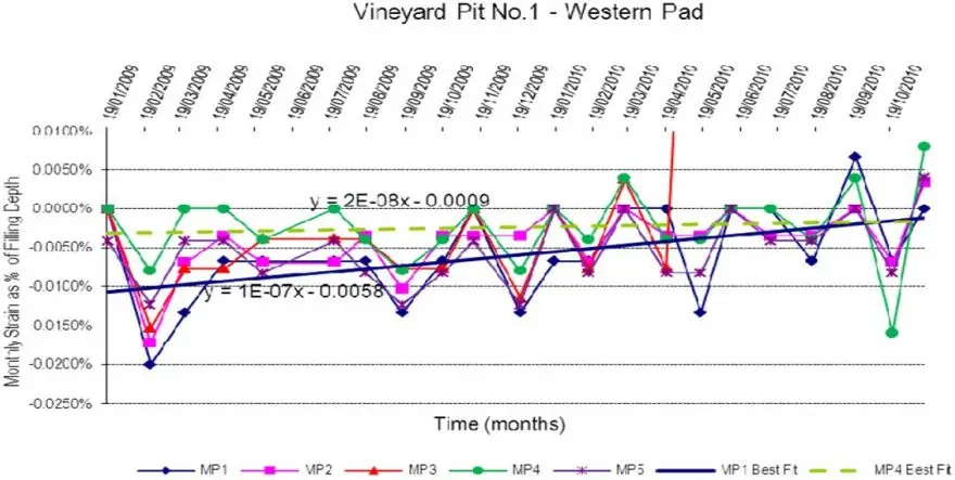
Figure 1: Percentage Strain Versus Time for Higher Western Half of Site (Area of Deepest Filling)
2.6 Comments
Considering the number of source sites that were required to backfill the quarry, the nature of the filling obviously varied. Together with the variations in filling depth, variations in filling performance across the backfilled quarry might have been expected. However, as the results of settlement monitoring clearly showed, the performance of the filling was reasonably consistent across all monitoring points across the site.
It was concluded that filling performance can be managed by implementing strict controls within earthworks specifications. In this case, controls were introduced for material types, compaction levels were linked to material types and moisture contents during compaction were tightly controlled. In addition, the specification and subsequent inspection and testing programme required all aspects of the various controls to be regularly checked by way of compaction and materials compliance tests. The site is being developed and settlement monitoring has ceased. The result is a filling volume that continues to perform well and within expected limits.
3. Case Study 2 – Sports Club in Western Sydney
3.1 Background Information
Case study 2 involves the construction of a sports club on a filled bench. As there were engineering problems with the site, the locations and names of the parties involved have been withheld.
One of the authors of the paper was asked to investigate the sports club building as it was showing signs of structural and movement distress. The building had large, floor to ceiling windows which were located between the tilt-up frame of the building and on the ground bearing slabs. The large windows allowed patrons of the club to enjoy the view of the sport fields and garden beds. Movements of 20 mm to 30 mm were observed across joints between the external tilt-up panels and internal walls.
A geotechnical investigation was carried out by others on the site in 1996 and a site classification of Class M provided in the report. Starting in June 1997, up to 2 m thickness of filling from the adjacent car parking areas was placed on the gently sloping site to provide a level building platform. The
clubhouse was constructed in 1998 and comprised tilt up reinforced concrete external walls founded on piers with a ground bearing slab. The tilt up walls had spaces for the windows to be placed between the panels and the ground bearing slab.
By November 1998, a number of defects which included outward bowing windows and relative movement between internal and external walls had been observed in the building. A structural engineer, in October 2000, considered that the cracking was a result of differential settlement likely to be the result of inadequate founding of the piers, poor filling compaction and moisture changes of the filling. Douglas Partners was asked to further investigate the cause.
3.2 Investigation Findings
Two pits excavated to expose the piers found that the piers were greater than 2 m deep and were founded in natural material. The pits also confirmed the presence of clayey filling to about 2 m depth.
Laboratory testing on the clayey filling provided the following results given in Table 3.

The results of the tests indicated that the filling was moderately reactive to changes in moisture content and was relatively “wet” compared to optimum moisture content.
There were 12 density tests carried out on the filling during its placement and these were reviewed as part of the investigation. The density test results are summarised in Table 4.

The specification for the project was 98% Standard dry density ratio with no moisture content requirement. Based on the results given in Table 4, the filling has achieved the required compaction with an average density ratio of 102.6%. The average moisture variation was 2.3% dry of optimum. The average moisture content at the time of placement in 1997 was 17.4% while the moisture contents at the time of the investigation in 2000 ranged from 19.0% to 29.4% with an average of 23.2%. It is understandable that the average moisture content had increased because the samples were taken from below the garden beds immediately adjacent to the ground bearing slabs in an area open to the weather. The garden beds appeared to be well maintained and therefore would have been regularly watered.
A survey of the slab in November 2000 indicated that the levels of the perimeter of the ground bearing slab were generally 10 mm to 15 mm higher than the centre of the slab. Even allowing for construction tolerances, the trend from the survey was that the slab was bowed with either the edges swelling or the centre shrinking. The locations where the trend was not obvious were in areas where the outside of the building was paved such as near the entrance of the club and the loading bay
3.3 Comments
The evidence suggested that the cause of distress to the building was the moderately reactive clayey filling swelling due to changes in moisture content which caused the ground slabs to lift at the edges, in a phenomenon known as edge heave, adjacent to the piled tilt-up frame of the building. The situation was exacerbated by the clayey filling being “over compacted” with the moisture content at time of placement being well dry of optimum. A garden bed adjacent to the building also contributed to the problem as it allowed the clay to wet up due to rain and watering.
It would appear that the design of the earthworks and building did not take into account the reactive nature of the founding material otherwise there should have been moisture content and maximum density restrictions placed on the earthworks and recommendation to provide protection to the edge of the building from changes in moisture content.
Suggested repairs options included moisture barriers, removing the garden beds, providing a sealed apron around the building perimeter and improving the drainage.
4. Case 3 – Industrial Site in South-Western Sydney
4.1 Background Information
This case involves the construction of a relatively large industrial building on a cut and fill site. As there were design and construction problems with the site and the site was subject to legal proceedings, the names and locations have been withheld. One of the authors was acting as an expert witness in the case.
4.2 History
A geotechnical consultant carried out a geotechnical investigation at the site in 2001 which encountered a subsurface profile of residual silty clay over shale. Laboratory testing produced results indicating high plasticity clays with high shrink-swell potential and a low California bearing ratio (CBR). As the site was to be cut and filled to produce a level building platform, the consultant did comment that the residual clay was not ideal for use as engineering filling, but may be reused provided the filling was compacted “to a density strictly between 98% and 102% of SMDD and at a moisture content within 2% of Standard optimum moisture content”.
The civil engineer for the project ignored the geotechnical advice and produced his own specification which required filling to be compacted to “100% Standard” and referred to an Australian Standards test method number which was superseded eight years previously. No upper limit of compaction or any moisture content requirements were specified.
Filling, varying up to 2 m in depth, was placed and compacted in 2002. Twenty two density tests were carried out under Level 2 supervision and the results are given in Table 5.

Using the civil engineer’s specification, all tests passed. If the geotechnical engineer’s recommendations were adopted, 15 out of 22 density tests would have failed.
An industrial building was constructed over the filling in late 2002. By 2006, the building was showing signs of distress with relative movement of up to 50 mm between the piled building structure and ground bearing slabs (refer Figure 2).
4.3 Post Construction Investigations
There were at least three investigations carried out by different geotechnical engineers after construction. The investigations confirmed the subsurface profile of filling over residual silty clay and shale and found that the filling had a general consistency of at least stiff. A summary of selected laboratory test results from the investigations is presented in Table 6.
The post construction investigations indicated that the moisture content of the reactive clay filling had generally increased since the time of placement.

4.4 Comments
As the piles did not appear to have moved, it was concluded that the relative movement of the ground bearing slabs was mainly caused by the reactive clay filling swelling as a result of an increase in moisture content. The situation was exacerbated by the filling being over-compacted with a moisture content dry of optimum.
The movement is to be expected given that reactive clays swell significantly when compacted at high densities and low moisture contents (Chen 1975; Cox 1978).
As the concrete slabs were to be replaced for other non-geotechnical reasons, the recommendations for repairing the damage due to the swelling clays on site was to remove the concrete slabs, remove and replace the top 1 m depth of filling and install subsurface drainage. The replacement of the filling was to be carried out using good engineering practice and strict density and moisture control of any reactive clay used as the replacement filling.
5. Conclusion
The case studies have shown that new filling, when placed and compacted using good engineering practice can be used for founding new buildings, even when placed to considerable depths. Similarly, the performance of filling can be managed by developing specifications that account for site specific conditions, including fillings that are constructed through importation of large filling volumes. When managed appropriately, the short term settlement performance of well-constructed filling can be used to estimate long term total and differential settlements, which has significant benefits when undertaking civil and structural design.
Moderately to highly reactive clay filling must be placed and compacted under strict guidelines as well as providing appropriate drainage, otherwise there may be long term problems as demonstrated by Case Studies 2 and 3.
References
Cox, D. W., “Volume Change of Compacted Clay Fill“, Proceedings of the Conference held at Institute of Civil Engineers, London, November 1979.
Chen, F. H., “Foundations on Expannsive Clay“, Amsterdam, 1975.
Download the PDF here.